
3-Bit-Ripple-Up-Counter:-
Counter:-
- A Counter is a device which stores the number of times a particular event or process has occurred, Counters are basically used to count number of clock pulses.
- Counter is a sequential circuit (mean output=present input+ past output).
- It is a group of flip-flops with a clock signal applied.
- There are two types of counter (depending upon clock pulse applied).

Difference between Synchronous and Asynchronous Counter:-
| Synchronous Counter | Asynchronous Counter |
|---|---|
| In Synchronous Counter all the flip flops are triggered by same clock simultaneously. | In Asynchronous counter all the flip flops are triggered by different clock, not simultanenously |
| Synchronous counter is faster than asynchronous counter | asynchronous counter is slower than synchronous counter. |
| In Synchronous counter any number of count sequences is possible. | In Asynchronous Counter only Fix Number of count sequence is possible. |
| Example:-Ring Counter, Johnson counter | Ripple Counter, Mod Counter |
 |
 |
Asynchronous Counter is also Known as Ripple Counter. If there are N Flip Flops then number of states are 2^N and Counter will counter from 0 to (2^N)-1. we can also classified Asynchronous Counter as Binary Asynchronous Counter and Non Binary Asynchronous Counter. Binary Counter has all states, but in Non Binary Counter there some states are missing. For Example if there are 3 Flip Flop then total possible states are (2^3)=8, but if we use only 5 states then it will be count as non binary counter.
there are two types of Binary Counter:-
- Up Counter
- Down Counter
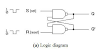
3-Bit Ripple Up Counter:-
If we use three flip flops for making a Asynchronous counter then it will called 3-bit Ripple Counter. this type of counter can be make using any type of flip flops such JK flip flop, T flip Flop etc. here i am defining 3-bit Ripple Up counter using T flip Flop with Negative Edge Trigger( when value of clock pulse goes from higher to law or 1 o 0 then flip flop will work).
The block diagram of 3-bit ripple counter is given below-

Key Points:-
- In above diagram 3- T Flip flops are used.
- As we know in Asynchronous Counter Different Clock is used for each Flip Flop so we provided external clock only to FF0 flip flop.
- The Output of flip flop FF0 is used as clock for flip flop FF1, same as output of FF1 is used as clock for flip flop FF2.
- Here Negative edge triggered is used mean is value of clock pulse is gone from 1 to 0 then Flip flop will work and toggle the previous value.
- Here Q0 is LSB and Q1 is MSB
| Condition | Operation |
|---|---|
| Let Initially all the flip flops are in reset state | Q2=Q1=Q0=0 |
| After applying first Negative edge Clock Pulse | Value of FF0 will be toggled, since Q0 value is changing from 0 to 1 so FF1 value no changed and FF1 Value is changing from 0 to 0 so flip flops FF2 will not change. Q2=0 Q1=0 Q0=1 |
| After applying second Negative edge Clock Pulse | Value of FF0 will be toggled, since Q0 value is changing from 1 to 0 so FF1 value will change from 0 to 1 and FF1 Value is changing from 0 to 1 so flip flops FF2 will not change. Q2=0 Q1=1 Q0=0 |
| After applying third Negative edge Clock Pulse | Value of FF0 will be toggled, since Q0 value is changing from 0 to 1 so FF1 value will not change and FF1 Value is Remain from 1 to 1 so flip flops FF2 will not change. Q2=0 Q1=1 Q0=1 |
| After applying Fourth Negative edge Clock Pulse | Value of FF0 will be toggled, since Q0 value is changing from 1 to 0 so FF1 value will change and FF1 Value is changing from 1 to 0 so flip flops FF2 will change 0 to 1. Q2=1 Q1=0 Q0=0 |
| After applying fifth Negative edge Clock Pulse | Value of FF0 will be toggled, since Q0 value is changing from 0 to 1 so FF1 value will not change and FF1 Value is Remain from 0 to 0 so flip flops FF2 will not change. Q2=1 Q1=0 Q0=1 |
| After applying sixth Negative edge Clock Pulse | Value of FF0 will be toggled, since Q0 value is changing from 1 to 0 so FF1 value will change and FF1 Value is change from 0 to 1 so flip flops FF2 will not change. Q2=1 Q1=1 Q0=0 |
| After applying seventh Negative edge Clock Pulse | Value of FF0 will be toggled, since Q0 value is changing from 0 to 1 so FF1 value will not change and FF1 Value is Remain from 1 to 1 so flip flops FF2 will not change. Q2=1 Q1=1 Q0=1 |
Truth table:-
| Q2 | Q1 | Q1 | CLK |
|---|---|---|---|
| 0 | 0 | 0 | 0 |
| 0 | 0 | 1 | 1 |
| 0 | 1 | 0 | 2 |
| 0 | 1 | 1 | 3 |
| 1 | 0 | 0 | 4 |
| 4 | 0 | 1 | 5 |
| 1 | 1 | 0 | 6 |
| 1 | 1 | 1 | 7 |


0 Comments
if u have any doubts please let me know,